
English 

T: +86-15800900153
E: songwenyan@windouble.com.cn
E: songwenyan@windouble.com.cn
No.1230, Beiwu Road, Minhang District,Shanghai,China
Views: 0 Author: Site Editor Publish Time: 2026-10-23 Origin: Site


Modern traction motors and high-speed industrial drives face a unique and demanding engineering challenge today. They require rotor position feedback capable of surviving extreme thermal, vibrational, and chemical environments without performance degradation. Traditional optical encoders often fail rapidly when exposed to severe shock, oil, or dust ingress. Furthermore, conventional wound-rotor resolvers introduce mechanical vulnerabilities through fragile rotary transformers and internal brushes. A variable reluctance resolver eliminates these rotor windings entirely. This specific technology relies on a solid, passive rotor design, offering a highly robust alternative for demanding motor control ecosystems. This guide provides a clear framework for evaluating, specifying, and integrating these sensors into your next project. We will focus closely on magnetic design trade-offs, fault tolerance strategies, and supplier shortlisting criteria. You will learn exactly how to balance accuracy and durability effectively.
Application Fit: VR resolvers are optimal for high-speed, harsh-environment applications (like EV/HEV powertrains) where durability outranks the sub-arc-second accuracy of optical encoders.
Design Topologies: Selecting between single-pole and multipole VR resolver designs directly impacts electrical error averaging and signal-to-noise ratios.
Risk Mitigation: Successful implementation requires rigorous modeling of air-gap eccentricity and fault condition analysis before finalizing stator lamination geometry.
Engineering teams must frequently compare standard operational limits when selecting feedback devices. Optical encoders provide excellent positional resolution but degrade quickly under high shock or particulate ingress. Standard wound resolvers handle harsh environments better but add unnecessary bulk to the motor assembly. They also introduce notable failure points via their internal rotary transformers and complex winding structures.
The primary advantage of VR technology lies in its elegant passive rotor architecture. The stator houses both the primary excitation windings and the secondary signal windings. The rotor itself contains zero copper wire. Instead, it relies purely on specific magnetic saliency to modulate the magnetic field as it spins. This deliberate simplification yields immense mechanical resilience against vibration and centrifugal stress.
You should specify this technology when your project meets the following ideal success criteria:
Extreme Temperature Tolerance: Your application requires continuous sustained operation in harsh environments reaching 155°C to 200°C, where optical sensors melt or distort.
Structural Durability at Speed: Your motor operates at exceptionally high RPMs. Traditional wound rotors risk severe mechanical disintegration under such intense centrifugal forces.
Strict Volume Constraints: Your mechanical assembly demands a low-profile, "pancake" form factor to minimize the overall length of the drivetrain.
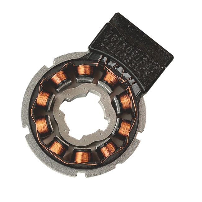
Choosing the correct stator winding topology directly influences manufacturing complexity and signal purity. Engineers typically choose between overlapping and non-overlapping winding configurations. Non-overlapping, or concentrated, windings significantly reduce manufacturing time and minimize overall copper volume. However, they introduce a distinct technical trade-off. Concentrated windings tend to generate higher spatial harmonics. You must employ advanced harmonic filtering within your magnetic design to ensure clean signal output.
Next, you must select the appropriate pole configuration for your system. A single-pole unit provides absolute mechanical position over a full 360-degree rotation. We recommend this specific approach for simpler industrial control schemes requiring immediate basic absolute position data upon startup.
Conversely, a multipole VR resolver (frequently called a multi-speed resolver) aligns its internal electrical poles directly with the motor's pole pairs. This configuration averages out mechanical errors across multiple poles simultaneously. Minor machining tolerances and slight dynamic eccentricities become much less impactful. The outcome is vastly improved position accuracy. This reliable precision ensures smooth, ripple-free torque delivery in demanding EV traction motors.
Table 1: Comparison of VR Resolver Pole Configurations
| Feature | Single-Pole Design | Multipole Design |
|---|---|---|
| Absolute Position Capability | Full 360° mechanical cycle | Single electrical cycle only |
| Baseline Accuracy | Standard | High (due to mechanical error averaging) |
| Ideal Use Case | General automated industrial control | High-performance EV/HEV traction motors |
| Signal-to-Noise Ratio | Moderate | Excellent |
Successful mechanical integration hinges on precise magnetic modeling. The rotor profile and its resulting saliency design are paramount to system success. The specific geometric shaping of the rotor lobes defines the sinusoidal permeance variation across the air gap. If the lobe geometry proves suboptimal, the resulting output signal will lack the required sinusoidal purity, frustrating your control loop.
Harmonic distortion control forms another critical design pillar. Open slot openings in the stator lamination stack easily cause unwanted spatial harmonics. Engineers must rigorously evaluate this risk early in the prototyping phase. We rely heavily on thorough Finite Element Analysis (FEA) to manage this. FEA allows you to optimize slot and pole combinations virtually. It minimizes harmonic interference long before cutting any expensive steel tooling.
Air gap tolerances require exceptionally strict attention. We must state a transparent assumption here. These passive-rotor devices are hyper-sensitive to air-gap variations. You must define rigid mechanical manufacturing thresholds during design. Tight tolerances prevent unwanted reluctance fluctuations and subsequent signal degradation over the product lifespan.
Best Practices for Mechanical Tolerances:
Specify strict bearing runout limits to minimize dynamic eccentricity during high-speed rotation.
Machine stator housings and rotor shafts to exact concentricity standards to ensure a uniform gap.
Conduct exhaustive thermal expansion modeling to ensure the air gap remains perfectly stable at 200°C.
Empirical engineering data highlights several common failure modes under realistic faulty conditions. You must address these operational risks proactively. Static and dynamic eccentricity frequently plague poorly mounted sensor assemblies. Off-center mounting severely affects the amplitude modulation of the generated sine and cosine signals. This physical imbalance translates directly into unacceptable angular position errors.
Internal winding short circuits also present a massive system risk. Inter-turn shorts impact the primary excitation field drastically. They distort the magnetic flux pathways and ruin the ultimate angular calculation entirely. Thorough insulation testing helps mitigate this threat.
Signal processing constraints further complicate successful implementation. The raw analog output demands a high-quality Resolver-to-Digital Converter (RDC) chip. During the initial prototyping phase, you must execute a thorough calibration process. This vital calibration compensates for inherent phase shifts and static amplitude imbalances between the sine and cosine channels.
For modern automotive applications, strict compliance with ISO 26262 ASIL standards remains mandatory. A highly reliable VR position sensor setup must include integrated built-in diagnostics. The selected RDC must detect sensor signal loss instantly to trigger safe-state motor shutdown protocols without hesitation.
Common Mistakes to Avoid:
Skipping detailed bench-level RDC calibration before advancing to full dynamometer testing.
Ignoring differential thermal expansion rates between the steel rotor core and the alloy motor shaft.
Failing to route delicate signal cables safely away from high-voltage PWM motor leads, inviting EMI.
Selecting the right manufacturing partner heavily dictates the ultimate success of your motor project. A highly qualified supplier must offer comprehensive prototyping and deep simulation capabilities. Standard generic datasheets are entirely insufficient for complex HEV/EV applications. You should actively look for comprehensive 3D magnetic simulation data. Demand concrete FEA validation reports that explicitly address spatial harmonic distortion mitigation strategies.
Next, carefully evaluate their engineering flexibility regarding customization versus off-the-shelf components. Most modern traction motors require bespoke mechanical dimensions. Your chosen supplier must be fully capable of modifying internal stator lamination stacks. They must seamlessly adjust rotor lobe geometries to match your specific shaft dimensions and exact pole counts.
Finally, rigorously assess their quality control framework and compliance maturity. For the automotive and aerospace sectors, robust manufacturing processes are simply non-negotiable. Look for proven Production Part Approval Process (PPAP) maturity across their portfolio. Ask detailed questions about their automated winding inspection capabilities. Verify their end-of-line electrical error testing protocols to guarantee consistent, flawless batch reliability.
The variable reluctance resolver remains the definitive feedback choice for high-reliability, high-temperature motor control applications. This success holds true provided your engineering team rigorously manages vital air-gap tolerances and harmonic optimization. By eliminating the fragile rotary transformer, you secure a highly resilient feedback device capable of surviving the harshest powertrain environments imaginable.
To move your integration forward effectively, consider these action-oriented next steps:
Request baseline 3D CAD models and comprehensive FEA reports from your shortlisted component suppliers.
Procure dedicated evaluation kits early to begin RDC pairing and baseline signal characterization immediately.
Conduct rigorous bench testing to validate amplitude imbalances under simulated dynamic eccentricity conditions.
Finalize your precise mechanical mounting strategy to guarantee strict concentricity between the rotor and stator.
A: Conventional resolvers rely on a fragile rotary transformer to induce necessary voltage into moving rotor windings. This traditional approach adds mechanical complexity, vulnerability, and weight. In stark contrast, VR resolvers utilize a solid steel, completely passive rotor carrying zero windings. They generate position feedback by relying purely on varying magnetic resistance, or reluctance, as the lobed rotor spins within the stationary stator field.
A: A multipole design cleverly creates multiple electrical cycles during a single physical mechanical revolution. This architecture effectively multiplies the sensor's baseline tracking resolution. More importantly, it mechanically averages out dynamic eccentricities, machining tolerances, and minor manufacturing imperfections across all the electrical poles simultaneously. This averaging significantly reduces overall angular position errors, delivering noticeably smoother motor commutation.
A: The typical accuracy generally ranges between ±10 to ±30 arc minutes. This specific figure depends heavily on the internal pole count, overall sensor size, and mechanical manufacturing precision. While this accuracy is lower than that of high-end optical encoders, it remains exceptionally stable across extreme temperature variations and intense vibration profiles where optical sensors would instantly fail.
A: Yes, but it depends heavily on the specific design. A single-pole unit provides true absolute mechanical position immediately upon startup. A standard multipole unit provides absolute electrical position only. This electrical data is perfectly sufficient for standard continuous motor commutation. However, if your control system absolutely requires mechanical position at startup, you will need to implement a wake-and-shake routine.