
T: +86-15800900153
E: songwenyan@windouble.com.cn
E: songwenyan@windouble.com.cn
No.1230, Beiwu Road, Minhang District,Shanghai,China
Views: 0 Author: Site Editor Publish Time: 2026-10-20 Origin: Site


Motion control failure in heavy automated machinery rarely happens because a motor burns out. Instead, these costly shutdowns often stem from feedback sensor fragility. Optical and magnetic encoders frequently fail under extreme environmental stress. This exposes a massive vulnerability in continuous-process operations. You need components built to survive these harsh realities. A ruggedized solution becomes essential where delicate optics shatter and standard electronics melt.
We provide engineers and procurement teams an objective framework here. You will learn how to evaluate, specify, and integrate electromechanical resolvers into demanding automated systems. We cover the business case, mechanical form factors, and integration risks. This guide gives you the practical knowledge to make resilient motion control decisions.
Durability dictates selection: Resolvers lack onboard electronics, making them the standard for high-temperature and high-vibration automation environments.
Form factor impacts integration: The choice between frameless and housed models directly affects mechanical assembly complexity and space constraints.
Conversion is a system-level consideration: Specifying a resolver requires parallel evaluation of the Resolver-to-Digital Converter (RDC) for latency and resolution requirements.
Objective trade-offs: While resolvers excel in durability, they typically offer lower absolute precision compared to high-end optical encoders, requiring a precise match to application success criteria.
Downtime in continuous-process automation creates immediate cascading delays. When a single feedback loop fails in a robotic welding cell or a heavy stamping press, the entire production line stops. Engineers often trace these failures back to a shattered optical encoder disk or a fried sensor circuit. Optical and magnetic sensors contain fragile silicon. They simply cannot survive the violent shocks and heat spikes common in heavy manufacturing.
To prevent these failures, you must redefine your operational success criteria. Many teams over-specify components by demanding ultra-high precision. However, true success in heavy automation means maintaining reliable precision under constant environmental stress. You need a feedback device designed to endure.
This reality makes a resolver for industrial automation incredibly valuable. Resolvers rely on underlying electromechanical physics rather than fragile circuitry. They function as analog rotary transformers. The design consists of a rotor and a stator wrapped in copper windings. They contain no delicate optics, no glass disks, and no onboard silicon chips. This robust physics-based design allows them to survive environments that destroy standard encoders.
We see resolvers deployed heavily in specific target applications. Consider these common use cases:
Extreme temperature zones: Steel mills and aerospace environments where temperatures exceed 200°C.
High-shock machinery: Stamping presses, forging machines, and mining excavators experiencing violent mechanical impacts.
Contaminated environments: Pulp and paper processing or agricultural automation featuring heavy fluid, dust, and particulate ingress.
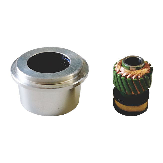
Once you decide to use a resolver, you must choose the appropriate mechanical form factor. Your choice directly dictates the mechanical assembly complexity and spatial footprint on the machine. Engineers typically select between frameless and housed models.
Frameless resolvers consist of two separate components. The manufacturer supplies the rotor and the stator independently. You mount the rotor directly onto the host motor shaft. You then mount the stator into the motor housing. This category works best for deep integration. Applications requiring minimal weight and highly compact footprints benefit heavily from frameless designs. However, this approach brings distinct trade-offs. The Original Equipment Manufacturer (OEM) must provide high-precision mechanical mounting. You must ensure strict concentricity between the rotor and stator to avoid signal errors.
Conversely, a housed industrial resolver offers a self-contained unit. It includes its own bearings, a dedicated shaft, and a rugged protective casing. This design shines during retrofitting projects on existing machinery. You can mount it externally via mechanical couplings. It also provides immediate environmental protection out of the box, often meeting IP65+ standards. The main trade-off involves space and maintenance. The larger footprint consumes more physical space on the machine. Additionally, it introduces internal bearing wear as a long-term maintenance variable.
Comparison Chart: Frameless vs. Housed Form Factors
| Feature | Frameless Resolvers | Housed Resolvers |
|---|---|---|
| Components | Separate rotor and stator | Self-contained with shaft and casing |
| Integration Depth | Deep internal integration | External mounting via couplings |
| Space Requirement | Highly compact | Larger mechanical footprint |
| OEM Responsibility | Strict concentric mounting | Basic external coupling alignment |
| Maintenance Factor | No internal bearings to wear out | Requires internal bearing monitoring |
Specifying the correct component requires careful evaluation of electrical and physical dimensions. You must match the resolver capabilities directly to the motor geometry and the ambient environment.
First, evaluate speed and pole pairing. You must match the number of resolver poles to the motor poles. This matching ensures optimal commutation feedback for brushless motors. A standard single-speed resolver features two poles (one pole pair). It provides absolute position feedback within one single mechanical revolution. In contrast, multi-speed resolvers use multiple pole pairs. They offer higher accuracy over electrical degrees but cannot provide absolute mechanical positioning without additional software tracking. You must decide whether your machine needs absolute positioning or higher incremental accuracy.
Next, scrutinize the environmental specifications. Standard encoders often fail at 100G of shock. A well-built industrial motor resolver routinely withstands shock levels exceeding 200G. You should assess continuous operating temperature ranges against your machine's thermal profile. Resolvers routinely operate smoothly at 150°C to 200°C, a threshold where optical encoder electronics melt.
Finally, understand the vital distinction between accuracy and resolution limitations. A resolver features theoretically infinite resolution because it operates as a continuous analog transformer. However, practical resolution is strictly bottlenecked by the capability of the Resolver-to-Digital Converter (RDC). We recommend managing expectations around typical accuracy. Resolvers generally achieve an accuracy of ±10 to ±30 arcminutes. This falls short of ultra-precision optical alternatives, but it remains remarkably stable under extreme stress.
Engineers often debate whether to deploy an encoder or a resolver for a new machine build. Making the right choice requires aligning sensor strengths with specific operational hazards. This framework helps you shortlist the right technology based on environmental facts.
You should mandate an industrial resolver under specific extreme conditions. Specify them immediately if your application involves temperatures exceeding 120°C. They also serve as mandatory components in heavy radiation environments, such as nuclear facilities, where silicon degrades rapidly. Furthermore, choose this technology when severe mechanical shock is a daily operational reality. They are highly preferred when you can safely locate the control electronics inside a remote cabinet, far away from the dangerous motor environment.
Conversely, you should specify an optical or magnetic encoder under different circumstances. Encoders remain necessary for ultra-high-precision applications like multi-axis CNC machining. They excel in low-vibration environments where thermal stability is guaranteed. Choose encoders when your control system requires a direct digital signal output without relying on external analog conversion devices.
Evaluate the ambient temperature at the motor casing.
Measure the expected shock and vibration forces during maximum load.
Determine the absolute precision required by the final manufactured product.
Assess the physical distance between the motor and the control cabinet.
Integrating these analog sensors into modern digital control systems introduces unique engineering challenges. You must anticipate these risks during the design phase to ensure flawless machine operation.
Cable length and signal degradation present the most common integration hurdles. Unlike digital encoders, resolvers transmit low-voltage analog signals. These signals suffer from attenuation over long distances. High electromagnetic interference (EMI) exists in noisy industrial plants. Heavy drives and contactors easily corrupt analog position signals. You must use high-quality, shielded, twisted-pair cables. Ground the shield properly at the controller end to mitigate noise injection.
You must also account for Resolver-to-Digital Converter (RDC) latency. The RDC sits between the analog sensor and the digital PLC or drive. It requires a finite amount of time to process the sine and cosine signals. This tracking rate and conversion latency impact high-speed dynamic control loops. If the latency becomes too high, the motor drive may experience phase lag, resulting in unstable velocity control.
Mechanical alignment faults pose another significant risk. When integrating housed units, improper mounting or coupling backlash introduces physical phase shift errors. The controller interprets this backlash as position error, leading to poor motor performance. Use high-stiffness couplings and ensure strict axial alignment during installation.
Finally, address the specific calibration requirements. You must perform phase tuning during initial setup. Ensure you match the correct excitation frequency between the motor drive and the sensor. Drives typically supply an excitation frequency ranging from 2kHz to 10kHz. Supplying the wrong frequency alters the transformation ratio and severely degrades signal accuracy.
Specifying a ruggedized feedback sensor represents a defensive engineering choice. It prioritizes machine uptime and environmental resilience over ultra-fine, fragile precision. When optical devices fail under heat and shock, these electromechanical transformers keep your automated lines moving.
Prioritize environmental durability over theoretical precision when specifying feedback devices for heavy automation.
Carefully evaluate whether a frameless or housed form factor best matches your assembly capabilities and space constraints.
Consult closely with your motor drive manufacturer to verify RDC compatibility and excitation frequency matching.
Conduct prototype testing in the actual machine environment to identify and mitigate EMI susceptibility before full production rollout.
A: Synchros and resolvers are both rotary transformers, but they serve different historical purposes. Synchros use 120-degree phase shifts across three stator windings. Engineers primarily used them for visual dial indication in older aviation and naval systems. Resolvers use 90-degree orthogonal windings (sine and cosine). This mathematical relationship makes resolvers ideal for precise modern motor control and digital conversion.
A: Yes, it can. A standard single-speed resolver features one pole pair. Because it outputs a unique combination of sine and cosine voltage amplitudes for every angle, it provides true absolute position feedback within one full mechanical revolution. If the machine loses power, the sensor instantly reports the correct position upon restart without needing to home.
A: Start by checking the excitation voltage at the drive to ensure the sensor receives power. Next, use a multimeter to measure the winding resistance on the rotor and stator. Look for open circuits or internal shorts. Finally, verify the integrity of the cable shielding. Grounding issues or damaged cables frequently cause erratic analog signal fluctuations.