
T: +86-15800900153
E: songwenyan@windouble.com.cn
E: songwenyan@windouble.com.cn
No.1230, Beiwu Road, Minhang District,Shanghai,China
Views: 0 Author: Site Editor Publish Time: 2026-06-30 Origin: Site


Advanced robotics and heavy automation demand extreme precision under punishing conditions. Achieving high-accuracy absolute position feedback in large-aperture, direct-drive, or high-torque joints without sacrificing environmental resilience remains a profound engineering challenge. Engineers simply cannot afford sensor failures when handling heavy, dynamic payloads.
The automation industry is rapidly transitioning from traditional geared motors to large-diameter direct-drive systems. This structural shift inherently requires large-hollow-shaft feedback devices. Joint designs now demand a clear central path to route utilities directly through the center of rotation. Standard sensing devices frequently fail to meet these harsh physical and structural demands.
We will objectively evaluate the capabilities, integration realities, and distinct limitations of Size 160 VR (Variable Reluctance) resolvers. You will learn how these highly robust components handle extreme industrial conditions. We will also cover exactly what it takes to specify them correctly. This guide provides bottom-of-funnel clarity for your next heavy-duty automation project.
Form Factor & Fit: Size 160 provides a large hollow through-bore, ideal for routing cables, lasers, or pneumatics in robotic joints and rotary tables.
Durability: Variable Reluctance (brushless, no onboard electronics) design ensures survival in extreme shock, vibration, and temperature environments where optical encoders fail.
Precision Dynamics: Multipole (high-pole-count) configurations multiply electrical resolution per mechanical revolution, delivering necessary accuracy for heavy-payload positioning.
Integration Constraint: Requires precise mechanical alignment (concentricity) and specialized Resolver-to-Digital Converters (RDCs) for optimal signal processing.
Engineers consistently face physical bottlenecks when applying standard sensors to heavy automation. Small-frame resolvers and standard optical encoders severely limit the performance of large robotic arms. They also constrain aerospace actuators and heavy-duty CNC rotary tables. These traditional sensors cannot mount directly to massive, high-torque shafts.
To use a small sensor on a large shaft, you must introduce mechanical couplings. You might use gears, belts, or separate encoder shafts. Every mechanical addition introduces backlash. They create hysteresis and structural compliance. These parasitic mechanical errors compound quickly. They eventually ruin the overall positional precision of the system.
Alternative sensors face severe environmental vulnerabilities on the factory floor. Glass scales suffer from rapid contamination. Optical sensor read heads go blind the moment cutting fluids enter the housing. Condensation fogs delicate optical tracks easily. Standard magnetic encoders degrade rapidly under high continuous temperatures. Industrial environments actively destroy fragile components.
We must strictly define the success criteria for large-frame joint feedback. A viable solution must deliver an exceptionally high Mean Time Between Failures (MTBF). It must support zero-backlash direct mounting to large shafts. The sensor requires sufficiently high resolution to control dynamic torque loops. Finally, it demands extreme environmental tolerance against fluids, shocks, and intense heat.
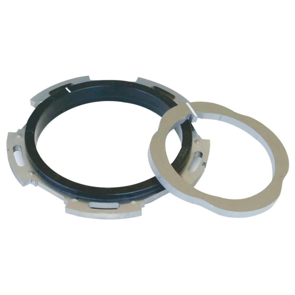
Understanding the fundamental design architecture reveals why this technology survives harsh conditions. The core of the VR Resolver Multipole Size 160 Series relies on Variable Reluctance physics. "Variable Reluctance" means the rotating component remains entirely passive. The rotor has no copper windings. It contains no magnets and no electronics.
All excitation coils and sensing coils are fixed permanently on the stationary stator. The rotor is simply a precisely machined piece of electrical steel. It features a specific lobed geometry. As this lobed rotor turns, it alters the magnetic permeance between the stator teeth. The stator coils detect this shifting magnetic flux to determine absolute position.
The "Size 160" designation highlights a distinct dimensional advantage. These units feature a nominal 160mm outer diameter. More importantly, this large footprint allows for an exceptionally generous internal bore. You can pass heavy power cables directly through the center. Engineers routinely route pneumatic lines, cooling channels, or laser beams right through the rotary axis.
High-pole-count designs elevate base resolver performance into precision territory. A standard resolver has one pole pair. It maps one electrical cycle to one mechanical revolution. A multipole design incorporates many pole pairs. Common configurations include 12, 16, or even 32 pole pairs.
The math behind multipole precision is straightforward. A higher pole-pair count divides any inherent mechanical error. It significantly increases the electrical resolution fed to the control system. If a rotor features 16 lobes, one full mechanical rotation generates 16 complete electrical cycles. This multiplier effect compensates heavily for the analog inaccuracies inherent in basic resolver technologies.
Engineers often weigh heavy-duty resolvers against large-bore optical encoders. Each technology dictates specific environmental and structural tradeoffs. You must match the sensor limits to your actual operating conditions.
Contamination destroys standard optical encoders. Dust, machine oil, and heavy condensation disrupt the light path. Optical ring encoders require strict, complex sealing mechanisms to survive machining environments. In contrast, VR resolvers offer near-total immunity to particulate contamination. Oil or water in the air gap barely affects the strong magnetic flux lines.
Shock and vibration tolerance present another stark contrast. Optical encoders rely on etched glass or fragile synthetic disks. Heavy impacts shatter them. Constant vibration misaligns their tiny read heads. VR resolvers utilize a solid metal rotor. They easily withstand immense physical shocks. You will often see them mounted directly next to heavy forging presses or industrial crushers.
Thermal constraints often dictate sensor selection in confined spaces. Direct-drive torque motors generate substantial heat. Optical encoders typically fail or lose accuracy around 85°C to 100°C. Their internal electronics degrade quickly past these limits. A pure VR resolver handles continuous operating temperatures in excess of 150°C. Some aerospace variants push reliably past 200°C.
We must maintain strict objectivity regarding accuracy tradeoffs. High-end optical encoders provide superior absolute base accuracy in clean, stable environments. They remain the gold standard for laboratory metrology. However, the multipole VR resolver bridges this accuracy gap effectively for heavy robotics. It sacrifices marginal micrometer precision to offer exponentially higher reliability in dirty, violent environments.
| Parameter | VR Resolver (Multipole) | Large-Bore Optical Encoder |
|---|---|---|
| Operating Temperature | Up to 150°C - 200°C | Typically limits at 85°C - 100°C |
| Contamination Resistance | Excellent (immune to oil/dust) | Poor (requires complex sealing) |
| Shock Tolerance | Extremely High (Solid Steel Rotor) | Low to Moderate (Fragile Disks) |
| Absolute Base Accuracy | Moderate to High (Multipole dependent) | Extremely High |
| Onboard Electronics | None (Completely passive) | Yes (Susceptible to heat/radiation) |
Successfully deploying a Size 160 resolver requires strict mechanical discipline. You cannot simply bolt it on and expect perfect output. A large-frame multipole resolver remains highly sensitive to rotor-stator eccentricity. If the rotor does not sit perfectly concentric to the stator, you generate severe harmonic distortion.
Eccentricity causes the air gap to vary as the shaft rotates. This uneven gap modulates the magnetic flux incorrectly. The host shaft requires extremely tight machining tolerances. Engineers must strictly control mechanical runout. You generally need mounting runouts kept below 0.02mm to maintain signal integrity across a 160mm diameter.
Raw analog outputs demand robust signal decoding. The resolver produces modulated sine and cosine voltages. These analog signals require a high-quality Resolver-to-Digital Converter (RDC). The RDC powers the primary coil and decodes the returning wave.
The control architecture must support specific excitation frequencies. High-pole-count signals generate high-frequency returns at rapid rotational speeds. The RDC tracking loop must process these dense signals without introducing phase latency. If the RDC bandwidth is too low, the calculated position lags behind the actual mechanical position.
Verify Host Shaft Machining: Ensure the mounting shoulder achieves tight perpendicularity and concentricity. Measure runout with a dial indicator before mounting the rotor.
Tune the RDC Properly: Match the RDC excitation frequency precisely to the resolver's specifications. Select a tracking rate that accommodates the maximum expected rotational speed.
Implement Strict Shielding: Route all analog sensor lines far away from high-voltage motor power cables.
Grounding Protocols: Ground the cable shield only at the RDC end. Grounding both ends creates a ground loop, which invites aggressive electrical noise.
Electromagnetic Interference (EMI) presents a constant threat. Industrial environments flood the area with electrical noise. High-voltage pulse-width modulation (PWM) from motor drives easily corrupts faint analog resolver signals. Always use heavily shielded, twisted-pair cables. Proper routing practices dictate the ultimate success of the control loop.
Certain industries mandate technology choices based purely on safety and certification hurdles. Aerospace and defense applications frequently baseline VR resolver technology. Actuators in flight control surfaces demand unquestionable reliability.
Aviation components undergo rigorous DO-160 testing standards. These standards measure resilience against violent vibration profiles. They test survival under extreme temperature cycling and high-G shock loads. The completely passive, rugged nature of the variable reluctance form factor passes these tests easily. They survive conditions that routinely destroy smart sensors.
Hazardous industrial environments also heavily favor this architecture. Facilities processing volatile chemicals or combustible dusts require explosion-proof equipment. Securing ATEX or IECEx certifications for complex electronics proves incredibly difficult and restrictive.
VR resolvers contain absolutely no onboard electronics. They lack capacitors, processors, or active components that might spark or overheat. This passive design makes them inherently easier to certify for Intrinsically Safe (IS) zones. When paired with an appropriate Zener barrier in the safe zone, they operate flawlessly in Zone 0 or Zone 1 explosive environments.
Specifying the right model requires matching the sensor dynamics to your motion controller. You should employ a straightforward rule of thumb. Whenever possible, match the resolver's pole count directly to the motor's pole count. This 1:1 ratio drastically simplifies commutation. The electrical angle of the resolver aligns perfectly with the electrical angle of the motor.
Evaluate your prototyping timelines carefully. Commercial-Off-The-Shelf (COTS) Size 160 units usually handle most standard heavy-duty applications. They provide predictable lead times. However, extreme environments often dictate customized variations.
Standard COTS Units: Feature electrical steel rotors and standard copper windings. Best for general robotics and CNC tables.
Custom Housing Materials: Titanium or specialized stainless alloys reduce weight and resist caustic chemical washdowns.
Custom Windings: Teflon-coated wires or specialized potting compounds extend thermal limits beyond standard ranges.
We highly recommend downloading the official 2D and 3D CAD models early in the design phase. Verify the spatial fit around your intended through-bore utilities. Ensure your chosen bearings leave adequate clearance for the stator housing. Once the physical fit is confirmed, contact an application engineer immediately to review your specific RDC compatibility.
The VR Resolver Multipole Size 160 stands as a highly specialized, intensely durable component. Engineers specify it strictly for scenarios where operational failure is not an option. It perfectly addresses applications that demand high accuracy while requiring a massive central through-bore for mechanical routing.
We urge you to double-check your mechanical runout tolerances before finalizing any specification. A robust sensor cannot overcome poor mechanical mounting. Strict machining practices unlock the true accuracy of the multipole configuration.
Take concrete action to secure your design. Access the detailed technical datasheets. Request a dimensional quote based on your pole-count needs. Most importantly, schedule a technical review with an application engineer to validate your exact environmental and control constraints.
A: Overall accuracy depends heavily on the chosen pole count and the strictness of your mechanical mounting tolerances. When mounted with excellent concentricity, a high-pole-count VR resolver typically delivers absolute base accuracy falling between ±1 to ±3 arcminutes.
A: Yes, but with a specific caveat. It provides absolute position feedback exclusively within one electrical pitch. To achieve full mechanical absolute position across a complete 360-degree rotation, it is frequently paired with a standard single-pole resolver or a dedicated multi-turn tracking track.
A: The exact requirements remain highly customizable based on your stator windings. However, they generally operate seamlessly within standard industrial control ranges. You will typically see excitation frequencies between 4kHz and 10kHz, utilizing voltages from 4 to 7 Vrms.
A: These devices are fundamentally "install and forget" components. Because they feature a completely brushless and bearingless design, there are no internal parts that wear out over time. Assuming your initial mechanical alignment is correct and remains stable, they require zero ongoing maintenance.