
T: +86-15800900153
E: songwenyan@windouble.com.cn
E: songwenyan@windouble.com.cn
No.1230, Beiwu Road, Minhang District,Shanghai,China
Views: 0 Author: Site Editor Publish Time: 2026-10-27 Origin: Site


Selecting a reliable feedback device for high-speed motor control presents a significant engineering challenge. Traditional optical encoders often fail in harsh environments. Magnetic sensors degrade heavily under extreme temperatures or severe contamination. You need a solution built to survive these conditions entirely without sacrificing precision. Today, the variable reluctance (VR) resolver stands out as the primary standard for robust traction and servo motor applications. It delivers reliable position feedback where other technologies break down completely. This guide provides a detailed technical evaluation framework to help you specify the right components. We will explore how to select multipole configurations based on your specific accuracy requirements. You will learn to navigate motor topologies and complex integration constraints effectively. By understanding these specific parameters, you can design highly efficient control systems for your most demanding industrial and automotive applications.
Matching the resolver’s pole pair count to the motor’s pole pairs is critical for optimizing the Resolver-to-Digital Converter (RDC) tracking loop and simplifying commutation.
A multipole VR resolver acts as an electrical gearbox, multiplying resolution and reducing the impact of mechanical alignment errors, though it introduces tighter tolerances for rotor concentricity.
Specifying a high resolution VR resolver requires balancing peak electrical error limits with the physical realities of stator-rotor air gap variations during thermal expansion.
Final selection depends on a verified matrix of transformation ratio, input excitation frequency, and environmental compliance (e.g., operating temperature ranges up to 150°C+).
Engineers face a common business and technical problem when designing modern control systems. Standard single-pole resolvers simply lack the necessary precision for advanced applications. High-pole-count electric vehicle (EV) traction motors require exact rotor positioning. Direct-drive industrial servos demand the same level of granular feedback to maintain stability. A single-pole device provides one electrical cycle per mechanical revolution. This 1:1 physical ratio severely limits the overall position granularity sent to the motor controller.
The multipole advantage solves this data bottleneck directly and elegantly. Engineers increase the number of salient poles on both the rotor and stator. This specific design choice increases the electrical cycles per mechanical revolution. Every mechanical turn now generates multiple sine and cosine waves. You effectively multiply your electrical position data without increasing the physical size of the unit. A multipole VR resolver transforms standard physical rotation into rich, high-frequency feedback.
However, these design gains introduce a strict engineering trade-off. Improvements in accuracy and signal-to-noise ratio (SNR) require tighter mechanical controls. The system becomes increasingly sensitive to mechanical eccentricities. Manufacturing tolerances must shrink to accommodate the complex magnetic flux paths inside the housing. You gain immense electrical precision across the operating speed range. In exchange, you must guarantee near-perfect mechanical alignment during the final assembly process.
You must evaluate several core dimensions before finalizing a specification sheet. The transformation ratio (TR) stands as your first primary metric. TR defines the necessary primary-to-secondary voltage ratio for the feedback loop. You must match this ratio to ensure compatibility across standard RDC chips. An incorrect TR leads directly to signal clipping or insufficient amplitude at the controller level.
Electrical error defines your actual system accuracy in real-world conditions. We typically measure acceptable peak-to-peak error in arcminutes. You must carefully differentiate between mechanical error and intrinsic electrical error. Mechanical error stems from poor mounting, bearing wear, or shaft runout. Intrinsic electrical error originates from the internal copper winding design itself.
Excitation frequency and voltage must align perfectly with your chosen hardware. You need to match the resolver's impedance and input requirements to your controller. A common specification might demand 10kHz at 7Vrms. Your drive controller's hardware capabilities must support these exact numbers. Otherwise, you risk poor magnetic saturation and weak return signals.
Finally, factor in the phase shift behavior of the electromagnetic circuit. Phase delay occurs between the excitation signal and the output sine/cosine signals. This delay fluctuates significantly across the operating temperature range. Your control algorithm must dynamically compensate for these thermal shifts to maintain efficiency.
| Evaluation Dimension | Technical Definition | Key Engineering Consideration |
|---|---|---|
| Transformation Ratio (TR) | The voltage scaling ratio between the primary excitation coil and secondary output coils. | Must strictly match the input limits of your selected Resolver-to-Digital Converter (RDC). |
| Electrical Error | The peak-to-peak deviation from an ideal sine/cosine output, measured in arcminutes. | Requires balancing intrinsic winding accuracy against realistic mechanical mounting tolerances. |
| Excitation Frequency | The AC frequency required to drive the primary coil (typically 5kHz to 20kHz). | High speeds demand higher frequencies to prevent signal aliasing during fast rotation. |
| Phase Shift | The time delay between the input excitation wave and the output feedback waves. | Fluctuates with temperature; requires dynamic algorithmic compensation in the motor drive. |
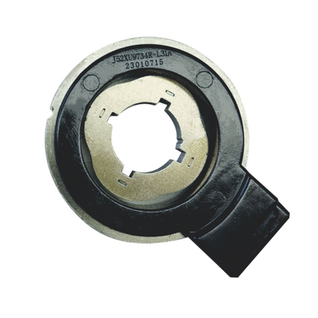
Motor topology alignment dictates your most critical design choice early in the project. The underlying logic demands matching resolver poles directly to motor poles. A 3-pole-pair permanent magnet synchronous motor (PMSM) contains six distinct magnetic poles. Therefore, engineers frequently specify a six pole VR resolver for these exact traction and servo applications.
This 1:1 matching strategy dramatically improves control loop efficiency. The electrical angle of the motor aligns perfectly to the feedback electrical angle. You eliminate the need for complex fractional mathematical compensation in the microcontroller. This direct correlation reduces processing latency in the Field Oriented Control (FOC) algorithm. Faster FOC loops enable smoother acceleration and higher peak efficiency at the rotor.
Failure to match pole counts introduces severe failure modes into the drive system. Mismatching creates complex harmonic distortion inside the position feedback loop. The controller struggles to parse misaligned electrical angles during rapid speed changes. This struggle manifests as noticeable torque ripple, especially at low operating speeds. Your motor will likely shudder or vibrate heavily during initial startup sequences. Always strive for exact pole parity whenever physical space limits allow it.
Many engineers confuse theoretical system resolution and absolute physical accuracy. Clarifying this difference prevents costly over-specification during the design phase. A high resolution VR resolver provides highly granular position data via the RDC. You might process a 12-bit or even 16-bit digital output signal. However, absolute accuracy remains bound by physical machining precision on the factory floor. High resolution simply slices a potentially inaccurate mechanical position into finer digital increments.
Multipole setups leverage an intrinsic electrical gear ratio to improve overall stability. This concept amplifies physical mechanical movement into multiple internal electrical cycles. The resolver inherently divides mechanical position errors by the number of pole pairs. If your rotor shifts slightly off-axis, the multi-pole averaging effect dampens the electrical spike. This averaging makes multipole designs inherently more stable than single-pole alternatives in high-vibration environments.
RDC interoperability dictates your maximum dynamic speed limits safely. You must select the right tracking rate on the analog-to-digital hardware. Fast traction motors spin at incredibly high RPMs under full load. If your RDC tracking rate falls behind, you experience severe signal degradation. The converter loses the electrical angle, causing immediate phase-current faults and system shutdowns.
Theoretical specifications often collide against harsh implementation realities on the assembly line. Radial air gap deviations represent your biggest physical constraint by far. Stator-rotor eccentricity directly introduces cyclical position errors into the controller. If the rotor mounts slightly off-center, the magnetic flux changes unevenly. This physical variation creates a predictable, repeating error curve on every single rotation.
Thermal dynamics also threaten long-term stability in harsh industrial settings. You must evaluate performance degradation at extreme operating temperatures. Traction motors frequently operate at continuous ambient temperatures of 150°C to 200°C. You must carefully assess the thermal expansion coefficients of your chosen materials. The resolver core expands at a different rate than the motor shaft. This mismatch can warp the delicate air gap under heavy load.
Electromagnetic interference (EMI) requires rigorous cabling discipline from the engineering team. High-voltage switching environments generate massive amounts of electrical noise. Silicon carbide (SiC) inverters switch rapidly, throwing EMI across the entire chassis. You must route excitation and signal cables carefully away from power lines. Proper twisted-pair shielding prevents induced noise on the sensitive sine and cosine tracks.
Follow this step-by-step shortlisting logic for your purchasing and engineering teams:
Verify the exact motor pole count to establish your baseline matching ratio.
Determine the maximum motor RPM and calculate the corresponding excitation frequency.
Set strict footprint, internal diameter (ID), and outer diameter (OD) spatial limits.
Select an RDC chip and verify its impedance and transformation ratio compatibility.
Request environmental test data confirming performance across your entire temperature spectrum.
Specifying a multipole feedback unit remains a delicate balancing act for system engineers. You must weigh theoretical electrical resolution against harsh mechanical mounting realities constantly. Excellent digital conversion cannot fix a poorly machined rotor shaft or loose bearings. Achieving true high-speed precision requires synergy between the electrical design and mechanical assembly.
We highly recommend requesting physical samples and CAD models early in development. Ask suppliers for detailed harmonic distortion test reports before committing to a final footprint. Real-world bench testing will quickly reveal any hidden thermal or eccentricity flaws. Identifying these issues early prevents catastrophic failures during final production validation.
Your next step requires engaging closely with chosen component suppliers. Discuss custom winding configurations if standard off-the-shelf transformation ratios fail your tests. Adapting the feedback unit to your legacy controller hardware often ensures the most reliable path forward. Clear communication regarding air gap tolerances will ultimately guarantee long-term motor control success.
A: Mechanical degrees measure the physical rotation of the rotor shaft. One full rotation equals 360 mechanical degrees. Electrical degrees represent the sine wave cycles generated during rotation. A multipole resolver generates multiple electrical cycles per physical turn. For example, a six-pole resolver creates three complete electrical cycles (1080 electrical degrees) in one single mechanical revolution.
A: We strongly recommend exact pole matching. Matching poles creates a 1:1 ratio between motor electrical angles and resolver electrical angles. This alignment simplifies your Field Oriented Control (FOC) algorithms significantly. It eliminates complex fractional math, reducing software latency. While software can compensate for mismatched poles, it often introduces unwanted low-speed torque ripple.
A: Optical encoders use a single reading point. If the glass disk mounts off-center, accuracy degrades severely. VR resolvers read magnetic flux across the entire circumference simultaneously. This multipole design inherently averages out minor eccentricity errors. However, excessive runout still warps the physical air gap, causing repeating cyclical electrical errors.
A: The optimal radial air gap typically ranges between 0.3mm and 0.5mm. You must maintain this gap tightly across the entire operating temperature range. Even a 0.05mm deviation can alter the magnetic flux paths measurably. Always account for the thermal expansion coefficients of your specific motor shaft and resolver stator.
A: A multipole VR resolver only provides absolute position within one electrical cycle. Because it repeats multiple cycles per physical revolution, it cannot identify the true mechanical starting angle on its own. You typically need a brief wake-up routine or an auxiliary sensor to establish absolute mechanical position at initial power-up.