
T: +86-15800900153
E: songwenyan@windouble.com.cn
E: songwenyan@windouble.com.cn
No.1230, Beiwu Road, Minhang District,Shanghai,China
Views: 0 Author: Site Editor Publish Time: 2026-08-15 Origin: Site


For motor control systems relying on a Brushless Resolver, specifying the correct excitation voltage and frequency is not just a datasheet formality—it is the baseline for preventing phase shift, signal degradation, and Resolver-to-Digital Converter (RDC) decoding errors. Mismatching the primary excitation input to your drive’s RDC limits leads to positioning failure. This problem escalates quickly in high-EMI industrial environments or high-RPM applications where signal integrity drops sharply. Unstable signals cause drive faults, sudden torque drops, and system paralysis. This guide breaks down how to evaluate excitation parameters, compare frequency constraints, and shortlist the correct resolver specifications for your application architecture. You will learn exact methods to align primary coil demands with converter inputs. We outline frequency selection frameworks, transformation ratio calculations, and hardware troubleshooting paths. Our goal is to ensure your final specification guarantees continuous synchronization.
Excitation voltage acts as the AC reference signal for the primary rotor winding, directly dictating the secondary output signals (Sine/Cosine) via the transformation ratio.
Choosing between a 5KHz Resolver and a 10KHz Resolver requires balancing motor RPM requirements against the capacitive loss of long cable runs.
Compatibility relies heavily on matching the resolver’s Transformation Ratio (TR) and excitation demands to your specific RDC chip (e.g., standard TI or ADI decoders).
Evaluating a Single Speed Resolver requires strict synchronization between the excitation cycle and mechanical rotation to guarantee true absolute position at startup.
You can think of this component as a specialized rotary transformer. The excitation voltage provides the fundamental energy source. Drive circuits typically supply 2 to 7 Vrms to power the primary winding. This current creates the magnetic field necessary to induce secondary Sine and Cosine voltages. The primary signal acts as a continuous carrier wave. As the rotor turns, the magnetic coupling varies. This variation modulates the carrier wave envelope. The resulting amplitude differences allow the system to calculate the exact mechanical angle.
Your excitation signal must align perfectly with the Resolver-to-Digital Converter’s reference input. The RDC acts as the brain of the decoding operation. It compares the primary carrier wave to the secondary return signals. Over-driving the primary coil causes voltage clipping at the RDC analog front-end. Clipping destroys the peaks of your sine waves, making angle calculation impossible. Conversely, under-driving lowers the Signal-to-Noise Ratio (SNR). When the signal drops too close to the noise floor, the RDC cannot distinguish real movement from electrical interference.
Poor excitation specifications carry heavy operational risks. Hardware engineers frequently troubleshoot angle decoding errors traced directly to bad voltage levels. In traction motors, these angle errors confuse Field Oriented Control (FOC) algorithms. The resulting phase misalignment produces severe torque ripple. Torque ripple wears down mechanical bearings prematurely. Eventually, signal-decoding faults trigger unplanned drive shutdowns. Properly matched excitation voltage remains the cheapest insurance against these catastrophic field failures.
Industrial applications often benefit from lower carrier frequencies. A 5KHz Resolver suits standard industrial automation and servo motors perfectly. Factory floors frequently demand long cable runs between the motor and the control cabinet. Long cables introduce parallel capacitance. This capacitance acts like a low-pass filter, attenuating high-frequency signals. Using a lower frequency prevents capacitive distortion. It ensures the signal envelope arrives at the drive intact.
Aerospace actuators and electric vehicle traction motors operate at extreme speeds. These applications require a 10KHz Resolver to sample angular changes fast enough. The Nyquist theorem governs this requirement. Your carrier frequency must be significantly higher than the electrical frequency of the rotating motor. If the excitation frequency is too low relative to the RPM, the RDC suffers from signal aliasing. A higher frequency prevents aliasing and reduces calculation latency.
Engineers must evaluate speed requirements against distance-to-drive constraints. Higher frequencies offer lower latency. However, they suffer greater transmission loss over extended cables. The table below outlines these technical trade-offs.
| Evaluation Parameter | Low-Frequency (e.g., 5KHz) | High-Frequency (e.g., 10KHz) |
|---|---|---|
| Maximum Motor RPM | Low to Moderate (< 10,000 RPM) | Extremely High (> 15,000 RPM) |
| Cable Length Tolerance | Excellent (Handles long runs) | Poor (Prone to capacitive loss) |
| Signal Latency | Moderate | Minimal |
| Core Material Losses | Low Eddy Current Loss | Higher Eddy Current Loss |
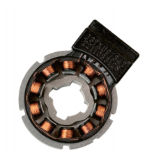
Transformation Ratio (TR) acts as the fixed multiplier for your sensor. It determines the maximum secondary output voltage based directly on the primary excitation input. Manufacturers commonly design units with a TR of 0.5 or 0.286. The internal coil winding turns dictate this ratio. You cannot change it in software. If you know the primary input, you can predict the exact secondary peak amplitude. This predictability forms the foundation of safe hardware integration.
Buyers must map TR calculations directly to their specific RDC maximum input thresholds. Ignoring this step guarantees hardware damage or tracking loss. We recommend following a strict evaluation sequence:
Identify the maximum Vrms output capability of your drive’s excitation oscillator.
Locate the Transformation Ratio on the sensor datasheet.
Multiply the primary Vrms by the TR to find the secondary maximum Vrms.
Compare this result against the RDC datasheet maximum input limits.
Adjust the drive software to lower the excitation amplitude if the result exceeds RDC limits.
For example, applying 7 Vrms to a unit with a 0.5 TR yields a maximum output of 3.5 Vrms. You must ensure your converter can handle 3.5 Vrms safely.
Higher excitation voltages demand more current. The drive’s oscillator circuit must supply this continuous power. Compact, integrated motor drives have strict thermal budgets. When you increase the primary voltage, you increase the heat generated inside the drive housing. Furthermore, lower impedance winding designs draw more current. Hardware teams must simulate this thermal load before finalizing the system architecture.
A Single Speed Resolver utilizes exactly one pole pair. This design maps 360 mechanical degrees directly to 360 electrical degrees. It delivers one complete electrical cycle per mechanical revolution. Therefore, it provides true absolute position feedback immediately upon power-up. The motor controller instantly knows the exact rotor angle. It does not need to perform a wake-and-shake routine. This absolute reliability makes it the standard for critical robotic joints and traction motors.
Implementing absolute positioning carries unique phase shift risks. The primary winding possesses internal inductance and resistance. When you inject an AC excitation signal, this internal impedance delays the magnetic flux. The secondary outputs trail behind the primary reference signal. This delay creates a phase shift. The excitation frequency directly alters this impedance interaction. Choosing the wrong frequency amplifies the phase shift, confusing the RDC timing registers.
Modern decoders handle minor phase shifts well. Chips from Texas Instruments or Analog Devices often include internal phase compensation registers. However, hardware engineers cannot rely on software alone. You must verify the specified excitation frequency minimizes raw phase shift at the hardware level. Industry standards typically require compliance tolerances below 10 degrees. You mitigate risk by matching the carrier frequency precisely to the manufacturer's tuned impedance specifications.
Mechanical eccentricities in rotor mounting ruin perfect excitation waves. If the rotor sits slightly off-center, the air gap changes dynamically during rotation. This uneven gap distorts the magnetic flux. The output voltage envelope will show an eccentric wobble. Specific excitation frequencies often magnify this wobble. Hardware testing parameters must account for mechanical runout. You should always measure the secondary envelope with an oscilloscope to confirm uniform concentricity.
Excitation lines emit strong electromagnetic interference (EMI). They carry high-frequency AC current. If you run them alongside sensitive return lines, the excitation signal bleeds over. You must prevent this crosstalk. Implement twisted-pair, individually shielded cables for all connections. Ground the shield at the drive side only to prevent ground loops. Never run excitation lines in the same wire bundle as high-voltage motor phase cables.
Integration issues frequently arise during the final prototyping phase. Simulated hardware environments, like SPICE or standard TI design tools, assume perfect conditions. They inject clean sine waves. Real-world drives use Pulse Width Modulation (PWM). PWM switching injects harsh noise directly onto the excitation line. Real-world noise causes unexpected decoding glitches. Hardware teams must filter the primary line carefully and avoid trusting simulation data blindly.
Your motor's maximum RPM dictates your frequency choice. Start by calculating the maximum electrical frequency your motor will reach. Choose an excitation frequency at least ten times higher than the electrical frequency. Evaluate carefully if a 10KHz model is strictly necessary. Do not over-specify the frequency if the application stays under 5,000 RPM.
Match the required Vrms excitation and Transformation Ratio to your drive's processing hardware. Read the analog front-end specifications carefully. Ensure your chosen sensor will not overdrive the chip inputs. Check the drive’s current output capacity against the primary coil impedance.
Evaluate the physical layout of your machine. Account for the total cable length from the motor back to the cabinet. Long cables demand lower frequencies. Factor in the operating temperature limits. High heat increases winding resistance, which subtly changes the phase shift. Ensure you have enough physical space for proper EMI shielding separation.
Do not base final decisions solely on datasheets. Encourage your mechanical team to request 3D CAD models to verify mounting dimensions. Have your electrical engineers verify RDC chip compatibility with the manufacturer. Always request prototype evaluation units. Bench-test the prototype using the exact cable lengths you plan to use in production.
The optimal excitation voltage and frequency are strictly dictated by three primary factors. You must balance maximum motor speed, total cable length, and the selected RDC threshold. While these rotary sensors are highly robust, their accuracy remains entirely dependent on the integrity of the primary signal. If the excitation fails, the entire positioning system fails. Avoid over-driving inputs, account for capacitive line losses, and shield your cables properly. We strongly recommend consulting with an application engineer to review your system architecture. An expert review ensures you select the correct unit and avoid costly redesigns.
A: Applying a higher frequency to a coil tuned for lower frequencies increases the internal impedance. This mismatch causes severe phase shift between the primary and secondary signals. You will also experience increased core losses, excess heat generation, and degraded positioning accuracy. The RDC will struggle to decode the trailing signal, leading to intermittent tracking faults.
A: Start by reading your drive and RDC specifications. Identify the maximum analog input voltage your RDC can accept. Check the sensor's Transformation Ratio (TR). Divide the RDC maximum input by the TR to find your maximum allowable excitation voltage. Always leave a 10% safety margin to prevent analog clipping.
A: Yes. Long cables introduce parallel capacitance and series resistance. This causes a noticeable voltage drop and capacitive coupling. The signal arriving at the primary winding will have a lower amplitude and altered phase. To solve this, use a lower carrier frequency or implement an excitation booster circuit at the drive output.