
T: +86-15800900153
E: songwenyan@windouble.com.cn
E: songwenyan@windouble.com.cn
No.1230, Beiwu Road, Minhang District,Shanghai,China
Views: 0 Author: Site Editor Publish Time: 2026-09-19 Origin: Site


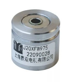
In mission-critical motor control systems, selecting the wrong position feedback device compromises system stability, safety, and project budgets. Electric vehicle traction drives, industrial servo presses, and aerospace actuators rely heavily on continuous, accurate data. While optical encoders offer peak precision in climate-controlled clean rooms, harsh environments demand the rugged reliability of a resolver. However, simply choosing a generic sensor is never enough. Spec-sheet misalignments frequently lead to control loop degradation, torque ripple, and eventual hardware failure. You must understand the specific technical parameters of your sensor perfectly. This guide breaks down how you evaluate and specify the exact parameters of a resolver. We show you how to ensure optimal integration with modern high-frequency motor control architectures. You will learn to navigate topologies, electrical matching, and pole pair configurations confidently.
Environment dictates typology: Brushless, variable reluctance, and housed resolvers each serve distinct mechanical and environmental constraints.
Electrical matching is non-negotiable: Transformation Ratio (TR), excitation frequency, and phase shift must perfectly align with your chosen Resolver-to-Digital Converter (RDC).
Poles equal performance: Matching the resolver’s pole pairs to the motor’s pole pairs simplifies commutation and maximizes absolute position accuracy.
Before looking at electrical specs, engineers must select the correct physical architecture. Space constraints, speed requirements, and environmental exposure guide this crucial choice. You have several primary designs to consider. Each offers distinct advantages for specific applications.
The brushless resolver sensor represents the industry standard for durability. A standard brushless design eliminates brush wear entirely. This creates a near-infinite theoretical mechanical lifespan. It uses a small internal rotary transformer to pass excitation signals directly to the rotor. We highly recommend this topology for continuous-duty industrial motor control. One drawback is the physical footprint. The internal rotary transformer requires extra axial length. You must account for this extra length in your motor casing design.
Alternatively, you might choose a variable reluctance resolver sensor for high-speed dynamic applications. This design contains no copper windings on the rotating part. Instead, a specially shaped metal rotor modulates the magnetic flux generated by the stator. This creates a highly compact, exceptionally low-inertia package. They easily handle extreme RPMs without risking rotor winding separation. Electric vehicle traction motors frequently use them. However, they can be more susceptible to specific electromagnetic interference (EMI) profiles. You must also maintain careful air-gap control during installation. If the air gap fluctuates, signal amplitude degrades quickly.
When deciding between a housed resolver sensor and a frameless unit, consider your assembly line capabilities. A housed unit comes completely factory-assembled. It includes its own precision bearings and a dedicated shaft. This enables rapid plug-and-play installation. It is much easier to retrofit into existing machinery or test rigs. The main tradeoff involves added mechanical complexity. You need flexible couplings to connect the sensor shaft to the motor shaft. Couplings can introduce minor torsional windup.
Conversely, frameless versions mount the rotor directly to the host motor shaft. This saves significant weight and valuable space. But frameless designs demand strict mounting tolerances. They require expert mechanical integration. Poor alignment leads to cyclical position errors ruining your control loop.
Once you choose a physical topology, you must align the electrical parameters perfectly. You will pair the sensor with a Resolver-to-Digital Converter (RDC). The RDC translates analog sine and cosine waves into digital angle data.
TR defines the ratio between the input excitation voltage and the maximum output voltage. The industry standard usually sits exactly at 0.5. Mismatched TR leads to RDC input saturation. Alternatively, a low ratio causes a poor signal-to-noise ratio (SNR). You must verify your RDC input limits match the sensor output voltage scaling perfectly.
Typical excitation frequencies span from 2 kHz to 20 kHz. Input voltages generally run between 4V and 7V RMS. Higher frequencies reduce phase shift. They improve dynamic tracking during rapid acceleration. However, high frequencies can increase capacitive coupling noise over long cable runs. Keep your cable length in mind when specifying your excitation frequency. Lower frequencies travel better over long distances.
Many engineers confuse accuracy and resolution during system design. The physical sensor dictates accuracy. We measure this mechanical error in arcminutes, such as ±10 arcmin. The downstream RDC dictates resolution. Resolution determines how many digital steps represent one full revolution. A 12-bit RDC provides 4,096 steps. A 16-bit RDC provides 65,536 steps. Avoid over-specifying sensor accuracy unnecessarily. If your mechanical system has significant gear backlash, an ultra-accurate sensor wastes engineering effort.
Resolver Electrical Specifications Reference
| Parameter | Typical Range | Impact on Control System |
|---|---|---|
| Transformation Ratio (TR) | 0.45 to 0.5 | Determines output voltage scaling for the RDC chip. |
| Excitation Frequency | 2 kHz to 20 kHz | Affects dynamic tracking capabilities and phase lag. |
| Input Voltage | 4 Vrms to 7 Vrms | Drives stator magnetic flux strength and signal clarity. |
| Accuracy | ±4 to ±20 arcmin | Defines the maximum absolute mechanical angle error. |
Pole count directly impacts the commutation of synchronous AC motors. You must align sensor poles to your system requirements. Incorrect pole counts complicate software engineering.
A single-speed design has exactly one electrical pole pair. It provides absolute position data over a full 360-degree mechanical rotation. This approach suits systems requiring an absolute startup position. It lets the motor drive apply full torque instantly upon boot. You avoid any complex wake-and-shake routines commonly seen in sensorless drives. Industrial robotics rely heavily on this single-speed capability for safe initialization.
Multi-speed designs match the sensor pole count directly to the motor pole count. For example, a 6-pole motor pairs best with a 6-pole sensor. This mechanical symmetry aligns the electrical degrees natively. It significantly reduces the computational load on your digital signal processor (DSP). You gain superior electrical angle accuracy. The mechanical errors average out across the multiple poles.
The primary engineering tradeoff is the loss of absolute mechanical position data. The sensor output repeats multiple times per mechanical revolution. A 6-pole sensor outputs three complete electrical cycles per one mechanical turn. You will not know the exact physical shaft angle without an external reference index. Best practices dictate mapping your motor poles carefully before ordering. A mismatch forces your microcontroller software to perform heavy mathematical interpolations. This introduces unnecessary latency into your fast control loops.
Motor control environments punish fragile electronic components. You must evaluate thermal limitations and mechanical vibration ratings carefully.
Standard industrial sensors operate comfortably between -40°C and 155°C. Aerospace or heavy-duty traction units can exceed 200°C. Extreme heat inherently alters the copper winding resistance inside the stator. Evaluate the sensor's temperature drift characteristics thoroughly. Ensure your chosen RDC can track and compensate for these natural amplitude variations. If the RDC lacks auto-compensation features, extreme heat heavily degrades angle measurement accuracy.
Heavy vibrations destroy glass optical encoders rapidly. Resolvers survive these conditions due to their robust analog construction. You must assess G-force ratings to prevent internal rotor and stator separation. Variable reluctance topologies inherently survive much higher vibration loads. They completely lack rotor windings. This removes a primary failure point under heavy shock.
Frameless architectures present hidden mechanical challenges. They demand extremely tight machining tolerances on your host motor shaft. Any concentricity error directly translates to cyclical position errors. You should monitor these key physical factors during installation:
Rotor-to-stator concentricity limits.
Axial alignment during final stator clamping.
Thermal expansion rates of the steel motor shaft.
Runout tolerances of the bearing assemblies.
Eccentricity creates an artificial modulation in the air gap. This causes a once-per-revolution error in your angle calculation.
System design involves continuous compromises. You must balance precision, physical durability, and supply chain realities.
We recommend a balanced application approach. Use Hall-effect sensors for simple block commutation where budgets are exceptionally tight. Choose optical encoders when you need peak positional precision in clean rooms. Specify a resolver when field failure is absolutely not an option. They thrive in environments featuring high heat, radiation, and heavy dust.
These sensors output low-voltage analog signals. They often operate right next to high-switching-frequency silicon carbide (SiC) inverters. Long cable runs in these noisy environments invite severe EMI corruption. You require specific twisted-pair wiring for the sine, cosine, and excitation lines. You must use heavily braided shielded cabling. Proper grounding at the RDC end prevents ground loops from distorting the delicate sine waves.
Custom winding configurations extend procurement lead times significantly. They trap you in a single-supplier dependency. Defaulting to commercial off-the-shelf (COTS) standard TR and impedance specifications ensures supply chain resilience. Standard parts guarantee you can source direct replacements quickly during a global crisis. Always prioritize standard impedance footprints unless the application strictly demands a custom winding.
Feedback Technology Comparison Chart
| Technology | Best Environment | Key Strength | Main Limitation |
|---|---|---|---|
| Resolver | Harsh, high-temperature, high-vibration | Extreme durability and reliability | Requires external RDC processing chip |
| Optical Encoder | Climate-controlled, clean environments | Ultra-high digital resolution | Fragile glass disks break easily |
| Hall-Effect | Basic industrial, space-constrained | Highly compact and simple integration | Low accuracy and poor resolution |
Specifying the right feedback device requires balancing physical mechanical constraints with your electrical architecture. You must align parameters like transformation ratio, pole count, and RDC compatibility perfectly.
Map the environment: Define the temperature and vibration limits your application will face in the field.
Determine pole count: Match the sensor poles to your motor poles to streamline commutation software logic.
Align electrical specs: Verify transformation ratio and excitation frequency match your control board perfectly.
Plan for EMI: Implement strict cable shielding protocols to protect analog signals from inverter switching noise.
Start your design process by building a clear profile of your mechanical constraints. Decide between housed or frameless designs early in the development cycle. Then, consult directly with application engineers. Request sample specification sheets to test mechanical fit on your bench. Always validate RDC compatibility in prototype systems before moving into volume production. Taking these steps guarantees a robust and responsive motor control system.
A: No. Multi-pole resolvers provide absolute electrical position within one pole pitch. However, the signal repeats multiple times per mechanical revolution. You cannot determine the exact mechanical angle of the shaft upon startup without additional sensors or wake-and-shake routines.
A: Traditional brushless units use a rotary transformer to pass power to rotor windings. Variable reluctance units have no windings on the rotor. They rely on a specially shaped metal rotor to alter the magnetic flux between stator coils. This makes them robust and capable of handling higher speeds.
A: The industry standard for most motor control applications is 0.5. Sometimes specific legacy RDC chips require 0.45 or custom ratios. Always verify your RDC specifications before ordering to avoid signal saturation.
A: Phase shift is the delay between the excitation signal and the sine/cosine output. It causes dynamic angle errors at high RPMs. You must quantify this delay so your RDC or DSP can digitally compensate for the lag during high-speed operation.