
T: +86-15800900153
E: songwenyan@windouble.com.cn
E: songwenyan@windouble.com.cn
No.1230, Beiwu Road, Minhang District,Shanghai,China
Views: 0 Author: Site Editor Publish Time: 2026-08-10 Origin: Site


Industrial motors often operate under extreme mechanical and thermal stress. Achieving absolute positional accuracy and precise commutation control in these harsh environments presents a massive engineering challenge. Standard sensors often fail when subjected to severe shock or high temperatures. A Brushless Resolver acts as a rugged, analog rotary electrical transformer. It essentially translates the rotor position into measurable electrical signals without any physical contact between parts. This non-contact baseline eliminates many common wear points found in traditional feedback devices.
Specifying the right feedback device directly impacts your motor lifespan, maintenance intervals, and overall system failure rates. If you choose poorly, you risk catastrophic downtime. In this comprehensive guide, you will explore how these robust sensors function inside a motor. We will also examine key architecture trade-offs and outline best practices for successful mechanical integration.
A brushless resolver provides absolute position and velocity feedback critical for servo motor commutation and motion control.
Unlike optical alternatives, their transformer-based, contact-free design guarantees operation in high-vibration, high-temperature, and contaminant-heavy environments.
Selecting between housed and frameless resolver architectures depends heavily on space constraints, bearing loads, and integration capabilities.
Proper implementation requires accounting for Resolver-to-Digital Converter (RDC) specifications, electromagnetic interference (EMI), and mounting tolerances.
Every highly dynamic motion system requires continuous feedback. A Motor Resolver serves this exact purpose by providing absolute feedback of the motor shaft's angular position. The device consists of a stationary primary winding and two secondary windings spaced 90 degrees apart. As the motor shaft turns, the resolver continuously monitors its exact physical angle. You always know the precise rotor location the moment the system powers on. It never needs to complete a homing sequence to find its starting point.
Older feedback technologies relied heavily on physical contact. They used fragile carbon brushes and slip rings to transfer electrical signals. These physical connections wore down quickly. They generated friction, caused electrical arcing, and introduced unwanted noise into the control loops. By entirely eliminating brushes and slip rings, modern transformer-based designs remove these primary failure points. You significantly reduce electrical noise and drastically extend the maintenance intervals of your motor assemblies.
To optimize torque and regulate speed dynamically, the motor controller needs to understand the rotor angle at all times. Here is how the device facilitates this process:
An external controller sends a high-frequency AC reference signal to the primary winding.
The magnetic field transfers across the air gap to the secondary windings on the stator.
The device outputs two distinct analog signals: a sine voltage and a cosine voltage.
The controller measures the amplitude of these two signals.
A Resolver-to-Digital Converter (RDC) processes this ratio to calculate the exact shaft angle.
This continuous analog data stream allows the motor drive to fire the stator coils at the precise moment required. It ensures smooth motion, eliminates torque ripple, and maximizes operational efficiency.
You cannot separate the physical sensing mechanism from broader business outcomes. When you integrate these robust sensors, you prevent catastrophic failures in mission-critical applications. In the aerospace sector, a failed sensor can ground an entire aircraft. In heavy automation, losing position feedback might crash a robotic arm into expensive tooling. The rugged analog nature of these transformers ensures steady operation. They safeguard millions of dollars in industrial assets by delivering uncompromised reliability.
Industrial applications rarely offer clean, temperature-controlled environments. Resolvers withstand extreme temperatures, often operating flawlessly up to 200°C. They tolerate heavy shock, intense vibration, and total submersion in oil. By contrast, optical encoders rely on fragile glass or plastic disks. High temperatures warp encoder disks. Heavy vibrations shatter them. A resolver relies on copper windings and steel laminations. You can essentially treat it as a solid block of metal.
Heavy particulate matter and condensation destroy optical transmission. If oil or water vapor enters an optical encoder housing, it refracts the LED light. The sensor immediately loses its position count and fails. Analog magnetic induction does not suffer from these vulnerabilities. Magnetic fields pass effortlessly through oil, dirt, dust, and condensation. This inherent signal integrity makes induction-based sensors the only viable choice for mining, paper milling, and heavy machining applications.
Engineers must carefully evaluate the initial component cost versus the long-term cost of downtime. Optical encoders often cost less upfront and provide direct digital outputs. Resolvers require external signal conditioning through an RDC, adding to initial panel costs. However, they almost never fail mechanically. When you calculate the hourly cost of unplanned downtime in a production facility, the superior durability offsets the initial electronics investment rapidly. You essentially trade a small increase in integration complexity for decades of uninterrupted service.
You need a clear logical threshold to guide your specification process. Use the following baseline criteria to determine the correct technology for your application.
Feedback Technology Selection Matrix
| Application Priority | Recommended Technology | Primary Justification |
|---|---|---|
| Harsh Environments & High Temperatures | Resolver | Tolerates up to 200°C, high shock, and survives heavy contamination. |
| Ultra-High Resolution & Clean Rooms | Optical Encoder | Provides millions of counts per revolution for precise semiconductor manufacturing. |
| Absolute Reliability & Zero Maintenance | Resolver | No internal wear parts, eliminating periodic replacement cycles. |
| Low Cost, Simple Digital Integration | Optical Encoder | Direct digital output eliminates the need for an external conversion chip. |
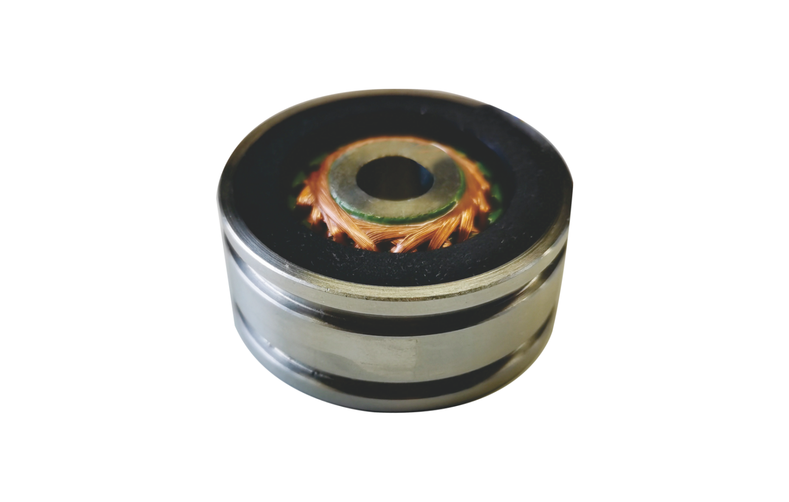
Manufacturers supply a Frameless Resolver as two separate components: a distinct rotor and a distinct stator. They do not include a housing, internal shaft, or bearings. You integrate them directly into the motor housing itself.
Reduced Overall Footprint: Embedding the sensor into the motor body saves critical axial length.
Elimination of Mechanical Backlash: Direct mounting to the main motor shaft removes the need for flexible couplings.
Fewer Components: Relying on the main motor bearings reduces the overall mechanical part count.
However, this architecture presents specific trade-offs. It requires much tighter mounting tolerances. Your facility needs in-house alignment expertise to ensure the rotor and stator remain perfectly concentric during assembly.
Configuration speed dictates the relationship between electrical cycles and mechanical rotation. A Single Speed Resolver completes exactly one electrical cycle for every full mechanical revolution. This one-to-one ratio provides absolute position feedback over a full 360 degrees. The motor controller always knows the exact angle immediately upon power-up.
Multi-speed variants feature multiple electrical cycles per mechanical revolution. A four-speed model generates four sine waves per rotation. This multiplies the effective resolution, making it ideal for high-precision machine tools. The trade-off lies in control complexity. Multi-speed units provide absolute position within one electrical cycle, but they cannot determine absolute mechanical position over the full 360 degrees without additional gearing or software tracking.
You must assess the acceptable error margins required by your specific application. Engineers measure resolver accuracy in arc-minutes. One arc-minute equals one-sixtieth of a degree. Standard industrial models typically offer accuracy ratings between 4 and 10 arc-minutes. If you design robotic joints or precise indexing tables, you might specify high-accuracy models trimmed to within 1 or 2 arc-minutes. You must balance this accuracy requirement against manufacturing costs, as tighter tolerances exponentially increase unit prices.
Do not rely on vague "ruggedness" claims. You must evaluate sensors through the lens of specific compliance standards. For food processing or heavy washdown environments, demand IP69K ratings to ensure survival against high-pressure, high-temperature water jets. If you operate in the aerospace sector, require MIL-STD-810 compliance to guarantee survival during extreme vibration and explosive decompression. For industrial explosive environments, look for ATEX or IECEx certifications to ensure intrinsic safety.
Physical constraints heavily influence the specification process. You must factor the unit into the available envelope of the motor housing. Weight also matters significantly in highly dynamic systems. The mass of the rotor adds inertia to the motor shaft. Excessive rotor inertia degrades acceleration rates and limits the dynamic bandwidth of the servo system. Always select the smallest, lightest form factor capable of meeting your accuracy and environmental requirements.
Your procurement strategy should prioritize vendor partnerships over simple component sourcing. Partner with manufacturers capable of providing robust testing data and extensive customization capabilities. Ask your vendor for transparent MTBF (Mean Time Between Failures) metrics based on empirical testing, not just theoretical calculations. A reliable vendor will supply custom lead lengths, specific connector types, and specialized potting compounds to match your exact environmental needs.
Real-world implementation often exposes mechanical vulnerabilities. Maintaining concentricity represents the greatest challenge during installation, especially when utilizing frameless models. If you mount the rotor off-center by even a few microns, you introduce eccentricity. Eccentricity causes the air gap between the rotor and stator to fluctuate during rotation. This fluctuation creates a once-per-revolution cyclic error in the output signal. You must strictly control shaft runout and utilize precise machining tolerances on your motor end-bells to minimize these alignment errors.
Analog signals are inherently susceptible to electromagnetic interference. High-power switching devices, such as Variable Frequency Drives (VFDs), generate massive amounts of electrical noise. If this noise couples into the feedback lines, it distorts the sine and cosine signals, causing erratic motor behavior. You must utilize twisted-pair, double-shielded cables. Route the feedback cables entirely separate from the high-voltage motor power lines. Furthermore, strictly adhere to proper grounding protocols, ensuring you ground the cable shield at the RDC end only to prevent ground loops.
The sensor alone does not dictate system accuracy. Overall performance depends heavily on the quality and tuning of the Resolver-to-Digital Converter. Modern RDCs utilize tracking loops to follow the analog signal. If the tracking loop bandwidth is set too low, the digital position data will lag behind the actual mechanical position during high-speed acceleration. You must carefully calibrate the RDC phase shift and excitation frequency to match the specific impedance of the sensor. Poor calibration directly results in velocity ripple and audible motor noise.
Extreme temperature fluctuations cause physical materials to expand and contract. You must evaluate the Coefficient of Thermal Expansion (CTE) of both the sensor materials and the motor shaft. If the motor shaft expands faster than the inner diameter of the rotor, it will create massive hoop stress. This stress can crack the rotor core or cause it to slip out of alignment. Conversely, stator expansion can cause the unit to bind inside the motor housing. Always ensure the mounting fits accommodate expected thermal growth across your entire operational temperature range.
Specifying the right feedback mechanism dictates the ultimate success or failure of your motion control system. Brushless resolvers deliver unmatched strategic value by safeguarding motor performance in the most demanding industrial applications. Their transformer-based construction entirely eliminates mechanical wear, ensuring absolute reliability in environments hostile to optical technologies.
Your choice between frameless designs, single-speed architectures, or multi-speed configurations must align directly with your environmental data and available integration expertise. Do not treat these sensors as commoditized afterthought components. Proper specification requires rigorous attention to mounting tolerances, EMI mitigation, and RDC calibration.
Take immediate action to secure your next motor design. Review comprehensive technical data sheets and analyze MTBF metrics. Request 3D CAD models from your vendor to confirm mechanical fits, and consult directly with an application engineer to validate your specific motor feedback requirements.
A: A traditional resolver relies on mechanical brushes and slip rings to transmit electrical signals to the moving rotor. These contact points cause friction, generate electrical noise, and wear out over time. Brushless variants utilize a rotary transformer design to transfer power and signals magnetically across an air gap. This completely eliminates physical wear parts, vastly improving the MTBF (Mean Time Between Failures).
A: Yes. Because they monitor continuous magnetic induction rather than counting digital pulses, they immediately report the exact rotor angle the moment you apply power. Single-speed models achieve absolute position over a full 360-degree rotation without ever requiring a homing sequence or battery backup.
A: The lifespan heavily depends on the architecture. Housed models are limited only by the mechanical life of their internal bearings, often exceeding 50,000 hours of continuous operation. Frameless models lack internal bearings entirely. Assuming proper installation and environmental protection, frameless units theoretically offer an infinite operational lifespan.
A: You must use a Resolver-to-Digital Converter (RDC). The RDC is a specialized integrated circuit that measures the ratio between the analog sine and cosine signals. It converts this analog ratio into a digital position word (often 12 to 16 bits). This digital data is then transmitted to your PLC or motor drive via standard industrial communication protocols.